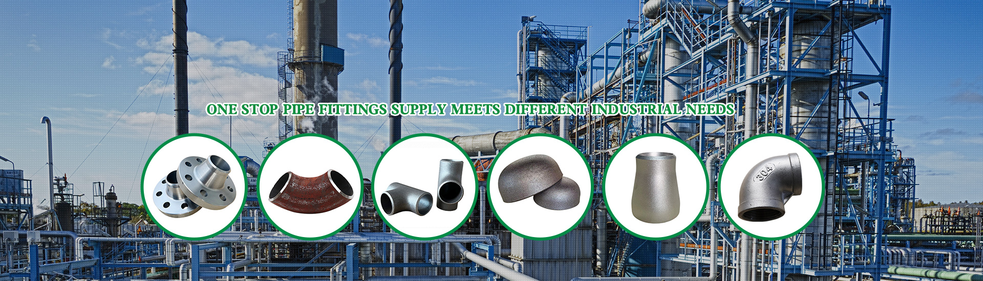
Pipe bending creates directional changes in piping systems without the discontinuities and potential leak points associated with fittings. Properly executed bends provide smooth flow paths that minimize pressure loss while reducing the number of welded joints requiring inspection and maintenance. Various bending methods address different size ranges, wall thicknesses, and geometric requirements, each with distinct capabilities and limitations.
Mandrel Bending Process
Mandrel bending uses an internal support tool that maintains pipe cross-section throughout the bend operation. The mandrel, typically a series of connected balls on a flexible shaft, follows the bend radius as the die rotates the pipe around a stationary form. This internal support prevents the flattening, wrinkling, and thinning that plague unsupported bending operations. The result is a smooth bore bend with consistent wall thickness distribution.
The mandrel configuration determines bend quality and the tightest achievable radius. Standard mandrels accommodate bend radii of 1.5 to 3 times outside diameter, with tighter radii requiring specialized tooling. Ball size selection affects inside surface finish, with larger balls providing smoother surfaces but limiting minimum radius. Mandrel extension beyond the tangent point influences bend quality at the start of the curve.
Material springback requires overbending beyond the target angle, with the amount depending on material properties and bend geometry. Steel springs back more than aluminum, and tighter radii exhibit greater springback than gradual bends. Skilled operators adjust bending parameters based on material and geometry to achieve accurate final angles. Computer-controlled machines store springback data for consistent results.
Induction Bending Technology
Induction bending heats a narrow band of pipe to bending temperature while the surrounding material remains cool. The heated zone becomes plastic while the cool pipe provides structural support, allowing controlled bending around a stationary form. Water sprays cool the newly formed bend area immediately, limiting the heat-affected zone and maintaining material properties. This process produces large diameter bends with excellent quality that would be impossible with cold bending methods.
The induction heating system precisely controls temperature through the bending zone, typically maintaining approximately 900 to 1100 degrees Celsius for carbon steel. Temperature monitoring ensures consistent results throughout long production runs. The heating and cooling rates affect microstructure and mechanical properties, requiring careful parameter control. Quench anisotropy influences final wall thickness distribution around the bend.
Induction bending suits large diameter and heavy wall pipe that cannot be economically bent using other methods. Offshore platform pipings, structural members, and power plant connections commonly use induction bends. The process accommodates diameters from approximately 4 inches through very large sizes, limited only by heating equipment capacity. Bend radii typically range from 1.5D through 5D or greater depending on size and wall thickness.
Hot Bending Considerations
Hot bending heats the entire pipe before forming, typically using gas furnaces or induction heating. The elevated temperature reduces forming forces and allows tighter radii than cold bending. Pipe sections are heated uniformly and then bent using mechanical or hydraulic force around a form. The heated pipe requires careful handling to prevent sag and distortion during forming and cooling.
Internal pressure during hot bending prevents ovality and wall thickening that would otherwise occur. The internal pressure balances external compressive stresses that would otherwise cause buckling. Fillers or sand inside the pipe maintain circular cross-section during bending. Internal supports similar to mandrel bending may also be employed for improved quality.
Heat treatment after hot bending restores or improves mechanical properties affected by the heating and forming process. Normalizing returns the microstructure to a uniform fine-grained condition. Quench and temper treatment develops specific property combinations where required. The additional processing cost and time must be considered in project planning and scheduling.
Compression and Ram Bending
Compression bending uses a rotating form around which the pipe is pulled while a pressure die follows behind. The outer radius compresses while the inner radius experiences minimal change, creating a bend with different wall thicknesses on each side. This method suits large diameter thin-walled pipe where other methods would cause collapse. The process is relatively simple and economical for appropriate applications.
Ram bending, also called press bending, forces the pipe over a stationary form using a hydraulic ram. The form radius determines the bend radius, with the ram applying force until the pipe conforms. This method produces significant wall thinning on the outer radius and thickening on the inner radius. The technique suits large structural members rather than pressure piping applications.
These simpler bending methods generally produce bends with reduced quality compared to mandrel or induction bending. Ovality, wall thinning, and surface wrinkling limit application to non-critical or low-pressure services. Thick-walled pipe resists distortion better than thin-walled sections, extending the usable range of these simpler techniques.
Quality Requirements and Verification
Wall thickness measurement verifies that bending has not caused excessive thinning that would compromise pressure capability. Ultrasonic thickness testing measures wall at multiple points around the bend circumference, comparing results to specification limits. Minimum wall thickness must remain above code-required minimums for the design pressure. Thinning beyond allowable limits requires rejection or requalification through pressure testing.
Ovality measurement quantifies cross-sectional distortion from circularity. The difference between maximum and minimum diameters, expressed as a percentage of nominal diameter, must remain below specified limits. Excessive ovality creates stress concentrations and may affect gasket seating if flanged connections follow the bend. Optical and mechanical gauges provide measurement capability for quality verification.
Visual examination identifies surface defects, cracks, and inappropriate wrinkles that may affect fitness for service. Magnetic particle or liquid penetrant examination detects surface cracks in ferromagnetic materials. Pressure testing confirms leak-free performance under design conditions. Hydrostatic testing verifies pressure containment capability for the as-bent geometry.
Applications in Industrial Systems
Process plant piping extensively uses bends to route through complex facilities while avoiding equipment, structures, and other piping. Long radius bends minimize pressure drop in critical process lines where pump head is limited. Custom bending for specific routing requirements eliminates multiple fittings and associated leak points. Computerized routing programs optimize bend placement and geometry.
Offshore platform piping requires numerous bends to navigate tight module layouts and structural interference. Induction bending produces the large diameter bends required for platform piping economically. Field bending on site addresses routing changes discovered during construction. Quality requirements for offshore service demand careful verification of bend quality.
Structural applications including handrails, guardrails, and architectural features use bending for aesthetic and functional requirements. Round tube bending creates smooth continuous members for these applications. Tube versus pipe selection affects bend quality and cost. Structural bends must meet both aesthetic requirements and loading capacity.
Specification and Documentation
Bend specifications must clearly define geometry, quality requirements, and testing expectations. Radius requirements coordinate with available tooling and production capabilities. Wall thickness limits, ovality tolerances, and surface quality requirements should reflect actual service needs. Overly stringent requirements increase cost without proportional benefit.
Material certifications ensure correct material reaches the bending operation and remains traceable after processing. Bending does not change material identity, but heat treatment may be required to restore properties. Heat numbers must be recorded throughout fabrication for traceability. Quality records document compliance with specifications.
Bend drawings show geometry, dimensions, and orientation for fabrication and installation. Isometric drawings commonly illustrate piping routing including bend locations and orientations. Three-dimensional modeling enables clash detection and installation verification before fabrication. As-built surveys document actual installed geometry.
Conclusion
Pipe bending methods range from simple compression bending through precision mandrel and induction bending processes. Method selection depends on pipe size, wall thickness, bend radius, and quality requirements. Quality verification ensures bends meet specifications for wall thickness, ovality, and surface condition. Proper specification and documentation ensure bending delivers the intended benefits of reduced fittings and improved flow characteristics.
References
American Society of Mechanical Engineers. (2022). ASME B31.3 - Process Piping.
American Society of Mechanical Engineers. (2021). ASME B16.49 - Factory-Made, Wrought Steel, Buttwelding Induction Bends.
Machine Design Reference. (2020). Pipe Bending Methods and Quality Standards.
Engineering, P. (2019). Bending Technology for Pipeline Systems. Industrial Press.