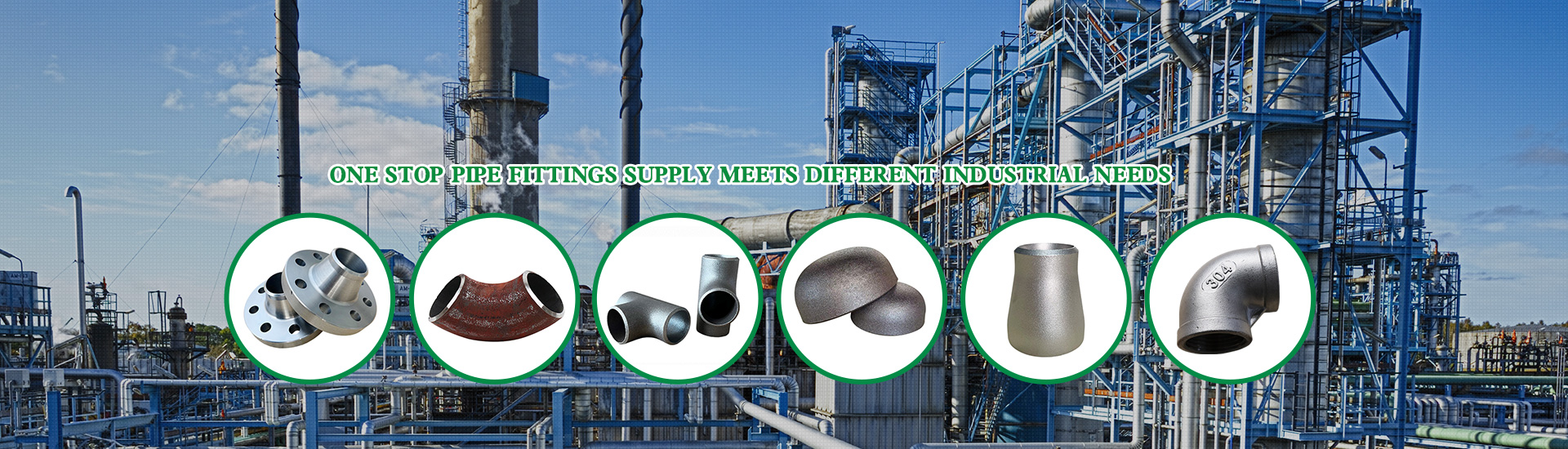
Reducers serve as essential transition components in industrial piping systems, connecting pipes of different diameters while maintaining flow continuity. These fittings appear throughout process facilities, from petrochemical plants to water treatment systems, enabling engineers to optimize pipe sizes for varying flow requirements. Understanding reducer types, their characteristics, and appropriate applications helps specifiers select optimal solutions for each unique installation.
Concentric Reducers: Design and Function
Concentric reducers feature a symmetrical design where the centerline of both ends aligns perfectly. This configuration creates a cone-shaped transition that gradually reduces diameter from larger to smaller pipe size. The concentric geometry maintains a straight flow path, making these reducers suitable for horizontal piping runs where air or vapor accumulation poses no concern.
Manufacturing concentric reducers requires precise forming operations. Hot pressing shapes heated plate material into the characteristic conical form, while cold forming produces closer dimensional tolerances for critical applications. Quality manufacturers maintain strict controls over wall thickness throughout the transition zone, ensuring adequate pressure containment at all points. The symmetrical design simplifies installation and alignment, reducing field labor costs compared to more complex configurations.
Applications for concentric reducers span numerous industries. Pump suction lines often specify concentric reducers to avoid air pockets that could cause cavitation. Vertical piping runs naturally suit concentric designs where gravity assists flow. Steam condensate return systems use concentric reducers without risk of vapor binding. The straightforward design proves reliable across decades of service when properly specified and installed.
Eccentric Reducers: Preventing Flow Problems
Eccentric reducers offset the centerlines of the two ends, creating an asymmetrical profile with one side remaining flat. This design proves invaluable in applications where liquid drainage or gas venting requires consideration. The flat side prevents accumulation of gases or liquids that could cause operational problems in horizontal runs.
Installation orientation determines eccentric reducer effectiveness. When placed with the flat side on top, these reducers prevent gas pockets from forming in liquid service. Conversely, flat-side-bottom installation promotes complete drainage in systems requiring empty capability. This flexibility enables engineers to address specific flow challenges through proper orientation selection.
Pump suction piping represents the classic application for eccentric reducers. Centrifugal pumps require flooded suction to operate reliably. Eccentric reducers installed with flat side up prevent air accumulation that could cause pump cavitation or loss of prime. Many specifications mandate eccentric reducers on pump suction lines for exactly this reason, protecting rotating equipment from vapor-induced damage.
Material Selection for Reducers
Reducer materials must match service conditions and adjacent piping system requirements. Carbon steel serves general purpose applications handling water, steam, and non-corrosive hydrocarbons. The material offers excellent weldability and competitive cost, making it the default choice for most industrial applications. Carbon steel reducers conform to ASTM A234 specifications, with various grades addressing different temperature and pressure requirements.
Stainless steel reducers address corrosion resistance requirements in chemical processing, pharmaceutical, and food industry applications. Type 304 stainless provides general corrosion resistance, while Type 316 adds molybdenum for improved resistance to chlorides and reducing environments. The material cost premium offsets against extended service life and reduced maintenance in corrosive environments.
Alloy steel reducers serve elevated temperature applications where carbon steel loses strength. Chrome-molybdenum grades like P11 and P22 retain strength at temperatures approaching 1100F, making them suitable for refinery process units and power plant steam systems. Material selection requires careful consideration of operating temperature, pressure, and fluid composition.
Dimensional Standards and Sizing
Reducer dimensions follow established standards ensuring interchangeability between manufacturers. ASME B16.9 specifies overall length, end dimensions, and tolerance requirements for wrought butt welding fittings. The standard covers sizes from NPS 1/2 through NPS 48, addressing most industrial applications. End preparation matches standard pipe schedules, enabling direct welding without special machining.
Pressure-temperature ratings for reducers coordinate with adjacent pipe ratings. Matching schedule or wall thickness ensures the reducer provides equivalent pressure containment capability. Thinner reducer walls would create weak points, while excessive wall thickness increases cost without operational benefit. Engineering specifications typically require reducers to match pipe schedule throughout the system.
Transition angle affects flow characteristics and pressure drop. Gradual transitions reduce turbulence and pressure loss but require longer fittings. Steep transitions save space but increase flow disturbance. Standard reducer lengths balance these considerations for typical applications. Custom reducers with extended transition zones address high-velocity applications where pressure drop minimization justifies additional cost.
Installation Best Practices
Proper installation ensures reducers perform reliably throughout system life. Butt welding preparations must match pipe end bevels, typically 37.5 degrees for standard wall thicknesses. Root gap consistency affects weld quality, requiring attention during fit-up. Tack welds secure alignment before completing circumferential welds.
Support considerations change at reducer locations due to diameter differences. Concentric reducers shift pipe centerlines, requiring support adjustment. Eccentric reducers maintain one side alignment, simplifying support requirements on that side. Hanger and support designs must accommodate diameter variations to prevent pipe sag or excessive stress.
Flow direction through reducers affects performance in some applications. Liquid flow from large to small diameter accelerates smoothly, while reverse flow may cause turbulence. Pump suction applications specifically require correct orientation. Documentation and labeling prevent installation errors that could affect system performance.
Quality Verification and Testing
Manufacturing quality directly impacts reducer reliability. Dimensional inspection verifies conformance to applicable standards. Wall thickness measurement confirms adequate material throughout the transition. Visual inspection identifies surface defects affecting weldability or service performance.
Material certification provides documented evidence of specification compliance. Mill test reports identify chemical composition and mechanical properties. Heat treatment records verify proper processing for materials requiring thermal conditioning. These documents support quality systems and provide traceability for critical applications.
Non-destructive examination detects internal defects before installation. Ultrasonic testing reveals laminations and inclusions. Radiographic examination of welds confirms proper fusion without porosity or cracking. Quality specifications define examination extent based on service criticality and applicable codes.
Conclusion
Reducers provide essential diameter transition capability in industrial piping systems. Concentric designs suit straightforward applications, while eccentric configurations address specific drainage or venting requirements. Material selection matches service conditions, and proper installation ensures reliable long-term performance. Working with quality manufacturers and following established standards provides confidence in reducer performance throughout system life.
References
American Society of Mechanical Engineers. (2021). ASME B16.9 - Factory-Made Wrought Butt Welding Fittings.
American Petroleum Institute. (2020). API 610 - Centrifugal Pumps for Petroleum, Petrochemical and Natural Gas Industries.
Tutorial, M. (2019). Piping Systems: Design and Application. Butterworth-Heinemann.
Crane Engineering. (2022). Flow of Fluids Through Valves, Fittings, and Pipe. Crane Company.